✨ Read this awesome post from Hacker News 📖
📂 **Category**:
📌 **What You’ll Learn**:
Crystal radios are famous for doing something almost magical: picking up broadcast signals with nothing more than a diode, an antenna, and a pair of headphones. They’re the simplest RF receivers you can build — and a brilliant way to learn how radio waves become electrical signals.
In this post, I’m taking that idea into the modern world. Using just two components — a high-speed Schottky diode and an LED — you can build a tiny “crystal detector” that responds to 2.4 GHz Wi-Fi, Bluetooth, and even microwave oven leakage. Unlike classic crystal radios, it doesn’t rely on a nearby AM transmitter, long wire antenna, or earth ground. Just the diode, the LED, and a small piece of metal for an antenna.
Despite the simplicity, it’s surprisingly effective. Bring it near a phone, router, laptop, or microwave oven and you’ll see packets and bursts appear as quick flashes of light. It’s easy to demonstrate in a classroom, easy to experiment with, and a great hands-on way to show how rectification and RF envelope detection work at microwave frequencies.
This circuit has a very minimal bill of materials, and does not require any soldering to complete, making it a great fit for a class-room activity.
Parts you’ll need
Assembly Instructions
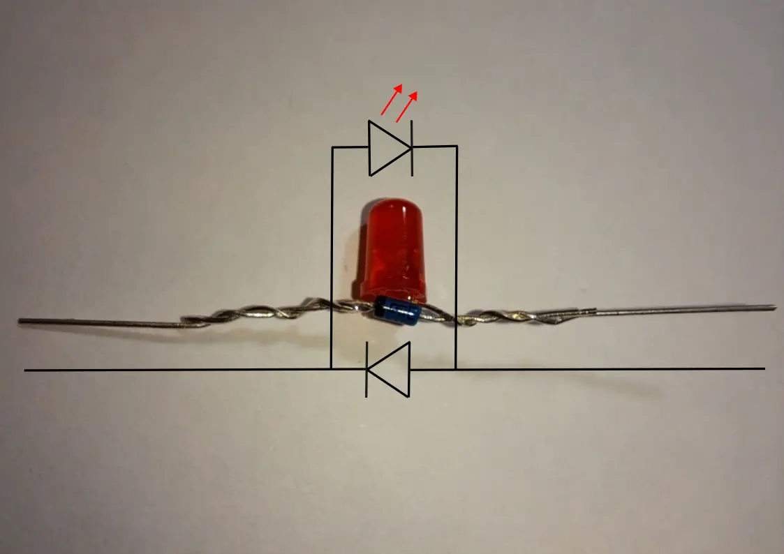
- Bend the LED legs so they extend horizontally in opposite directions. These form the antenna.
- Place the diode alongside the LED, with its legs parallel to the LED legs. Make sure the diode’s cathode is next to the LED’s anode.
- Twist the diode legs tightly around the LED legs.
Twist the diode legs as close to the LED body as possible — the snugger the connection, the more reliable the detector.
That’s it. You’re done.
You’ve now built a two-component detector for 2.4 GHz microwaves.
Hold it near a Wi-Fi router, smartphone, Bluetooth device, or even the front of a running microwave oven, and you should see the LED flicker or glow in bursts:
How It Works
This detector converts invisible RF energy into tiny flashes of light:
- As RF waves hit the LEDs legs, which act as a simple antenna, the diode allows charges accelerated by the radio waves to flow in only one direction.
- Positive charges gradually accumulate on the leg connected to the diode’s cathode.
- When enough charge builds up, the LED briefly lights, discharging the stored energy as a visible flash.
- Each RF burst repeats this process, so the LED flickers in sync with nearby 2.4 GHz signals.
Even with just a diode and LED, this demonstrates the same principle as a crystal radio: rectifying alternating currents and accumulating charge to drive a visible output.
Troubleshooting Tips
Ensure the Diode and LED Are Oriented Correctly
For the detector to work, the LED and 1N5711 diode must be connected the right way around:
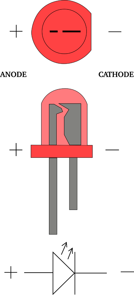
- LED:
- The anode is usually the longer leg.
- Inside the LED, the anode connects to the smaller internal element, while the cathode connects to the larger one.
- 1N5711 Diode:
- The cathode is marked by a black ring.
When assembling connect the LED’s anode (longer leg) to the diode’s cathode (marked with a ring).
Getting this orientation correct is essential — if it’s reversed, the LED will not flash. Refer to the diagram for a visual guide.
Works at 2.4 GHz Only
The 1N5711 is fast, but not quite fast enough for most 5 GHz Wi-Fi signals.
If a device is connected only on the 5 GHz band, this detector may show nothing.
For testing, start with a 2.4 GHz router, which produces lots of bursts that are easy to detect.
Don’t Touch the Legs
If your fingers touch the antenna legs, the LED may stop flashing.
Your body capacitance absorbs the tiny charge the circuit is trying to build.
A simple fix is to glue a small bamboo skewer or plastic stick to the LED body so you can hold it without interfering.
Try Different Angles
The LED legs act as a dipole antenna, which is polarized.
To get the strongest signal, the legs need to be aligned with the electric field of the transmitter — usually vertical for Wi-Fi routers, but this can vary.
Try slowly rotating the detector while watching the LED.
Component Selection Matters
This project won’t work with just any diode — it needs a very fast RF-capable Schottky diode.
Slower diodes can’t rectify 2.4 GHz signals, and the LED will stay dark.
I’ve tested this circuit with the 1N5711, and it consistently works.
It’s a good idea to start with that exact part before experimenting with alternatives.
For the LED: use a red LED.
Other colors require a higher forward voltage and may be significantly less sensitive or fail to light at all under weak signals. Red LEDs switch on at a much lower voltage, which is exactly what we want.
💬 **What’s your take?**
Share your thoughts in the comments below!
#️⃣ **#Beginners #TwoComponent #CrystalStyle #WiFi #Detector #Silicon #Junction**
🕒 **Posted on**: 1767472630
🌟 **Want more?** Click here for more info! 🌟