


🔥 Read this insightful post from Hacker News 📖
📂 **Category**:
✅ **What You’ll Learn**:
A little over a month ago, I ran into a Tektronix TDS7104 at the
Silicon Valley Flea Market,
where else?
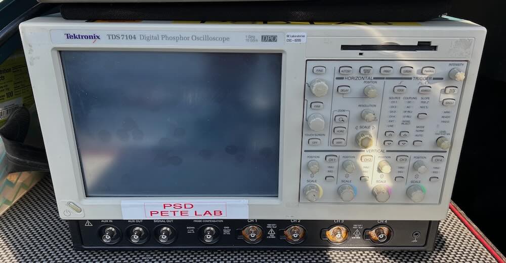
Other than some dirty buttons, a few smudges here and there, and the usual
assortment of calibration and asset tracking tags, the unit was in excellent
cosmetic shape, but the price tag of $700 was way out of line: as I write this
a try-before-you-buy TDS7104 can be had on Craigslist for the same price.
But Paul, the seller/liquidator, has a habit of saying “I’ll make you a deal”
and he did before I even asked: $300. That’s still a lot by flea market standards,
but a pretty good price for a TDS7104… if you can get it to work.
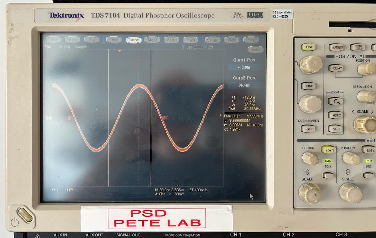
At home, the scope powered up right away and it booted straight into the main
scope application. Other than a screen that was way too dim, everything seemed
fine.
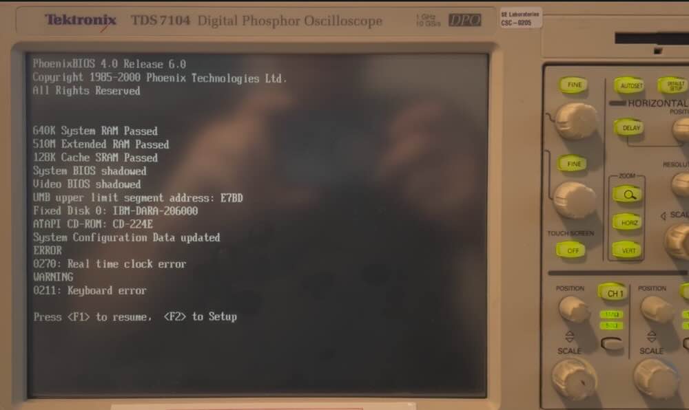
But when I tried it again a few hours later, it got stuck at the BIOS screen with
a CMOS battery error.
In this blog post, I go over the steps I took to get the scope back in top shape.
The TDS7104 is a 4-channel oscilloscope with 1 GHz bandwidth and a maximum sample
rate of 10Gs/s, though that’s only possible when using 1 channel. The sample rates
drop to 5 Gs/s for 2 channels and 2.5 Gs/s for 3 or 4. Even by today’s standards,
the specs exceed those of hobbyist class oscilloscopes, think Rigol and Siglent, though
there’s a price to pay in terms of weight, 39 pounds, and volume: they’re as wide and
deep as the earlier TDS700 series, for example, and much taller. The TDS7054 is its
little brother, figuratively speaking only. In the same chassis, it has a 500 MHz
bandwidth and 5 Gs/s.
Unlike more advanced TDS7xxx models, the 7104 and 7054 have BNC connectors instead of
custom Tektronix ones that require probes or adapters with prices that exceed today’s
price of the scope itself.
Introduced mid 2000, these scopes initially ran Windows 98 but they must have upgraded
soon after to Windows 2000 Pro Embedded, because that’s what mine has and it has components
with a late 2000 timestamp.
The PC motherboard has the little-used NLX form factor. Mine was a RadiSys SF810
with a Socket 370 and a 100 MHz front-side bus. Originally, these scopes shipped with
a dog slow 550 MHz Celeron, I got lucky with a 850 MHz Celeron. The fastest compatible
Celerons with 100 MHz FSB go up to 1.4 GHz, but they’re pricy. You should be able to
find 1.1 GHz versions for around $20 on eBay.
Unlike my Agilent 54831, the 640×480 LCD screen has resistive touch control which makes it
possible to use the advanced scope features without the need to connect a mouse.
In addition to the PC motherboard, there is a PowerPC-based controller board that runs
VxWorks like many other Tektronix products of that time, and a large acquisition board.
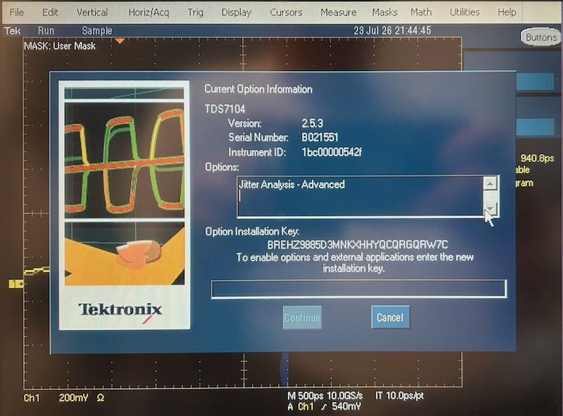
In addition to a few hardware options such as a 4M/channel sample memory, up from a 500k default,
there are plenty of software options for advanced measurements: jitter testing, USB certification
testing, etc. Both the software and hardware options can be enabled with a license key. To
the suprise of no one, that protection scheme was hacked long time ago…
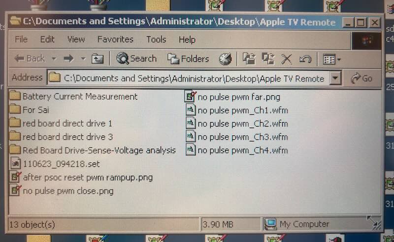
According to the labels on the chassis, my scope came from the PSD lab at Cypress
Semiconductor, where it was used for things like measuring high-bandwidth signals such as
the battery current on the Apple TV Remote. :o)
As always, you’ll find a bunch of hobbyists trying to revive this kind of scope on the
EEVblog forum, Youtube and some blogs. Here are the most common failures:
- PC motherboard CMOS backup battery dead
- PowerPC backup battery dead
- Hard drive dead
- Power supply capacitors leaking
I was lucky and only had to deal with issues 1 and 3, sort of.
A dead PowerPC backup battery will give you considerably more work than what’s described
in this blog post. After booting up the TekScope application will show the splash screen,
but it will hang there forever. You will need to:
- Take apart the scope even more and take out all the PC components:
floppy, HD, CDROM drive, motherboard. - Replace the top cap of the Dallas DS9034 NVRAM with a new battery.
- Connect with RS-232 to the PowerPC controller board.
- Enter a bunch of values to store in the NVRAM.
You can detailed step-by-step instructions here.
You should also check out this repair video by Feedbackloop.
A dead power supply is another common problem. It often will prevent the scope from
booting up at all. There are plenty of discussions about this on the Eevblog forum,
here
is one that has the reverse engineered power supply schematic attached. Often, all that’s
needed is to replace some leaking capacitors.
I didn’t have to do any of that…
Whether the machine boots or not, your first step should always be to make an image
of the hard drive, a 6 GB IBM Travelstar in my case.
Like my Agilent 54831,
I thought that I’d have to open the case to access the drive, but you can just push
on the spring-loaded black cover in the back and pull the drive sled out. Nice!
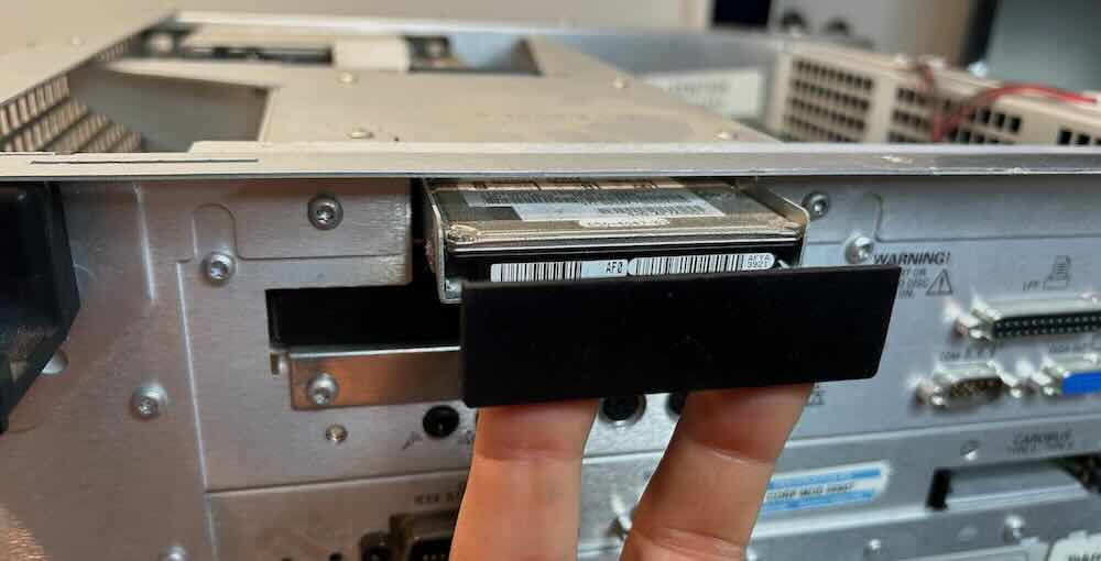
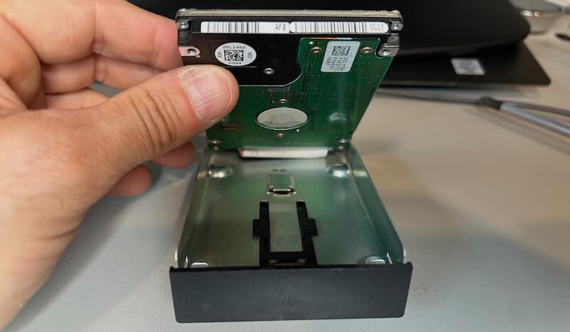
Remove the drive from the sled, plug it into a
USB-to-IDE adapter, and extract the data.
On Windows, I use HDD Raw Copy Tool.
I often use Linux for this kind of maintenance, but since this scope is a Windows 2000 machine,
I ended up needing a bunch of Windows-only tools.
The Travelstar HD was running on fumes, because HDD Raw Copy Tool ran into a number of corrupt
sectors during the copying operation. I was lucky, the impacted files were related to the French
Windows 2000 manual, but it shows the importance of making an image of the drive ASAP.
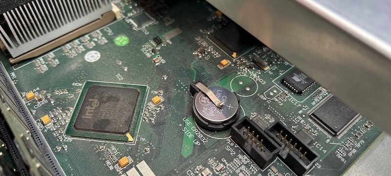
You’ll need to open up the case to get to the PC motherboard CR2032 backup battery.
See the next 2 sections for that.
After installing the new CR2032, the scope booted back up again, but the TekScope window
had some weird corruption and waveforms didn’t render right. This was because the
Chips & Technologies 69000 graphics card settings had been changed to a 256 color
palette mode. It needs to be set to True Color 24-bit mode.
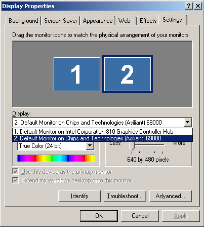
Notice the presence of 2 video cards: an Intel 810 integrated graphics card and
the Chips & Technologies 69000. The latter is responsible for driving the LCD
screen. It has special hardware to render oscilloscope waveforms in overlay mode:
they are sent by the acquisition board to the video memory through DMA
without CPU intervention.
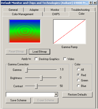
While we’re on the topic of the display: after installing the CR2032, the LCD display
was still very dim, to the point that I was researching replacement CCFL backlight tubes.
That turned out to be entirely unnecessary: the TDS7104 doesn’t have a way to control
the intensity of the LCD backlight. The previous users must have used it in a dark lab
and dialed down the brightness by adjusting the gamma settings in Windows:
I’m putting this section before the Disassembly one to make sure those with a low attention
span get the message: chances are high that you don’t need to remove the front panel.
And that’s good because, unlike the TDSnnn series scopes, the front panel has
some plastic tabs that are very easy to break. That said, even if you do break them (I did!),
the result is not catastrophic and you should be able to put the panel back firmly where it
belongs with no one noticing a thing.
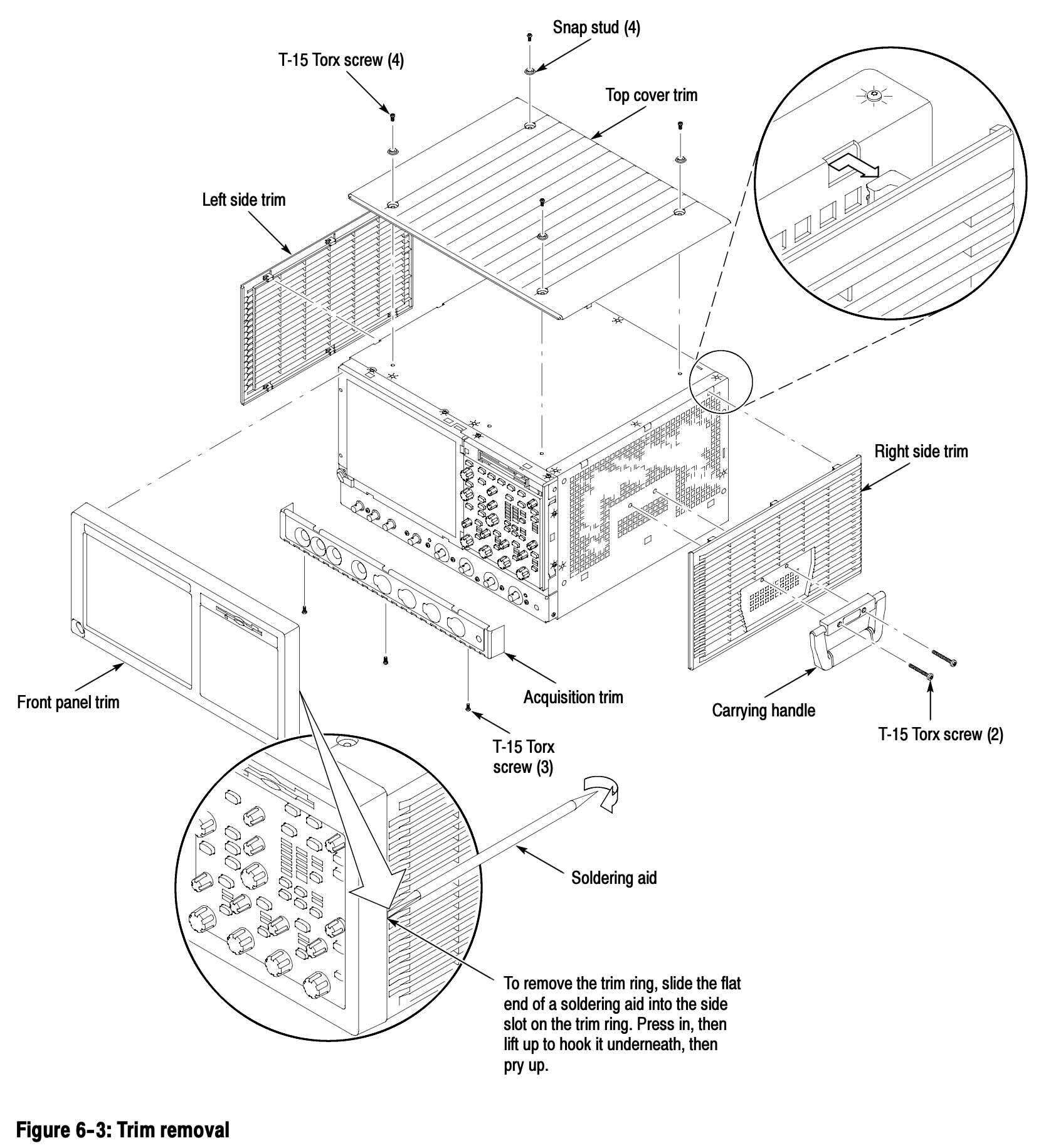
(Click to Enlarge)
The TDS7000 Series Service Manual
makes it sound easy enough:
To remove the trim ring, slide the flat end of a soldering aid into the side
slot on the trim ring. Press in, then lift up to hook it underneath, then pry up.
And from the pictures, it’s as if you can remove the front panel without removing anything
else. That just didn’t work…
The front panel consists of multiple click tabs: 1 on the left side, 1 on the right and then
a bunch at the top and the bottom. So far so good. However, the left and right side also
have 2 slide tabs that go into the metal rails. If you lift the left and right tabs too much,
these plastic slide tabs break off.
So you need to be very careful to make sure that you don’t lift the plastic trim too much,
and that you slide the panel out while it stays parallel with the display.
Or… you don’t touch it: you can do all PC maintenance, including replacing the floppy drive,
without removing the front panel.
I will continue my tradition of documenting the disassembly of test equipment in too much detail
because nobody else does it. Even though the service manual technically describes how
to do it, a few pictures go a long way to make it easier.
To access the inside of the scope, you need to remove more than 30 screws. On the plus
side, they’re all Torx-15 screws and they’re all the same length, so you don’t need
to worry about keeping track of which screw goes where.
Still, it takes a while and it validated my recent purchase of this
cordless screwdriver, recommended by Shrirar
over at The SignalPath.
Unbutton the accessory bag
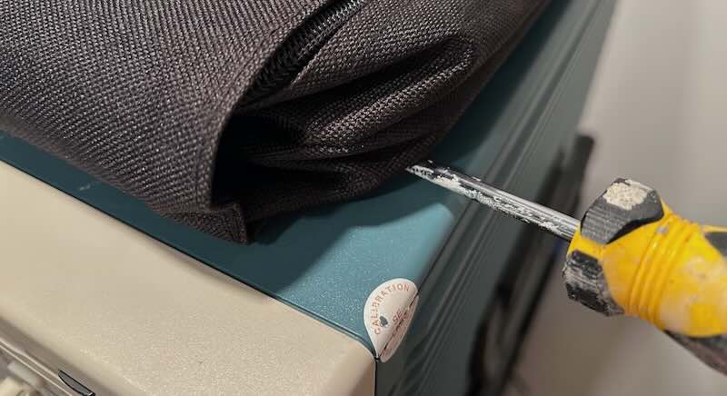
This took me longer to figure out than I want to admit: you can just unclick the bag
from the chassis, but the buttons can be very tight and if you’re not careful the fabric
can tear. Use a flat-head screwdriver right next to each button to lever it off.
Put the scope upright on its back feet
It’s an unusual arrangement, but the easiest way to dismantle the scope is by putting it
on its back feet: you don’t need to remove any screw from the back!
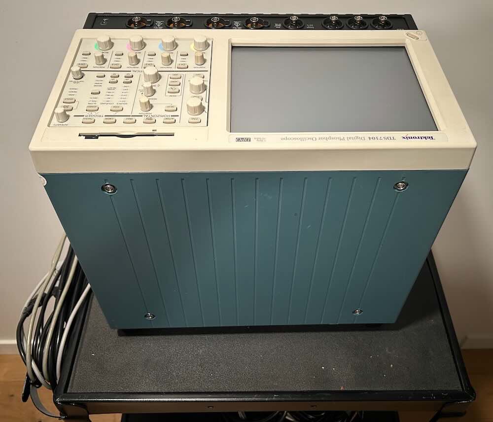
Let me once again sing the praises of a sturdy equipment cart: it’s so much easier to
walk around the cart than to muscle around bulky, heavy test equipment on a table.
Remove the top panel
4 screws through the accessory bag buttons (“snap studs”) fix the top panel to the chassis.
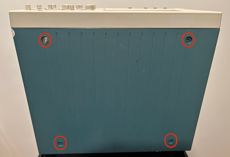
After removing this panel, you could remove the side panels already, but I found it much easier
to remove the bottom panel next.
Remove the bottom panel and loosen the black front connector trim
Next, remove the 5 screws of the bottom panel as well as 3 screws that keep the black trim
of the front BNC connectors in place.
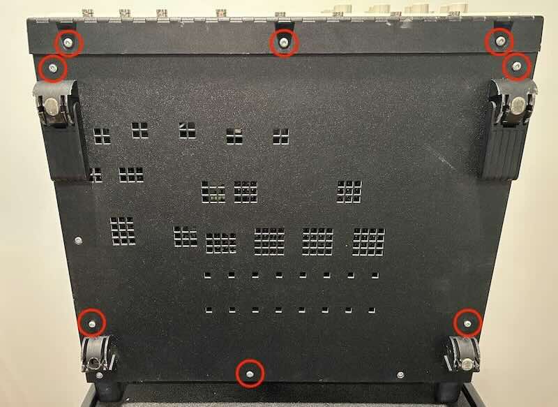
The black trim doesn’t need to be completely removed, only loosened because otherwise
it will soon be in the way of some other screws.
The bottom panel shall now be removed though. Just slide it down a bit and take it off.
In the picture above, you can see 2 screws that aren’t marked in red. That’s because they
don’t keep the bottom panel in place. But if you feel like it, you might as well remove them
now too.
Remove the handle and side panels
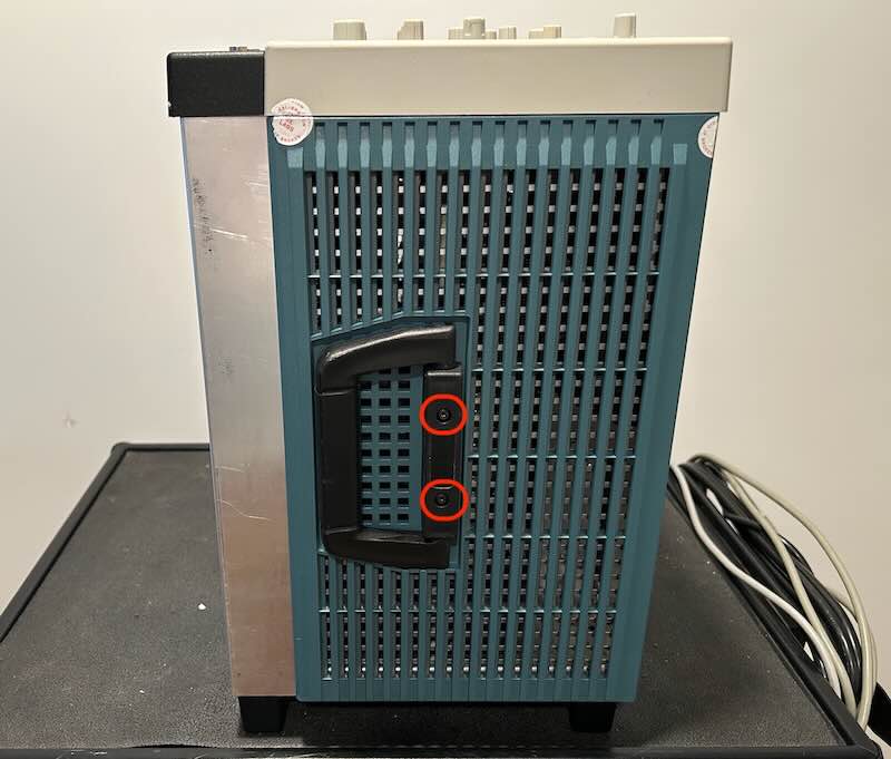
With the bottom panel gone, the side panels are a breeze to remove after unscrewing the
handle.
I lied: these 2 screws are different than the others. But they’re a different
color and impossible to get wrong.
Remove the 2 sheet metal parts
With the outer covers removed, you’re now staring at the sheet metal RF protection
enclosure. It consists of 2 parts, each part covers 2 sides. Remove all the screws,
take off the bottom part and then the top.
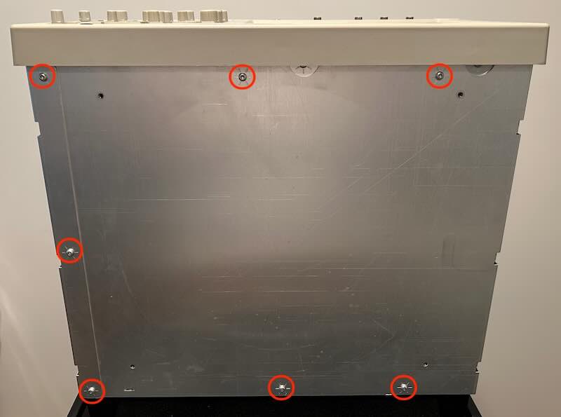
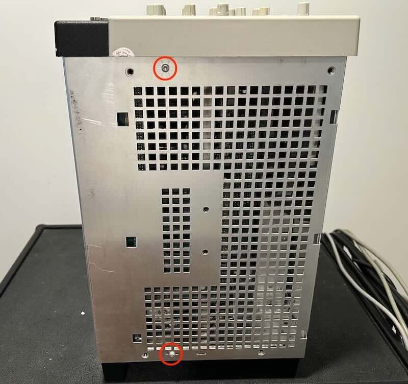
Note how some of the bottom screws are hidden underneath the BNC connector cover. That’s
why you had to remove its 3 screws of the black trim.
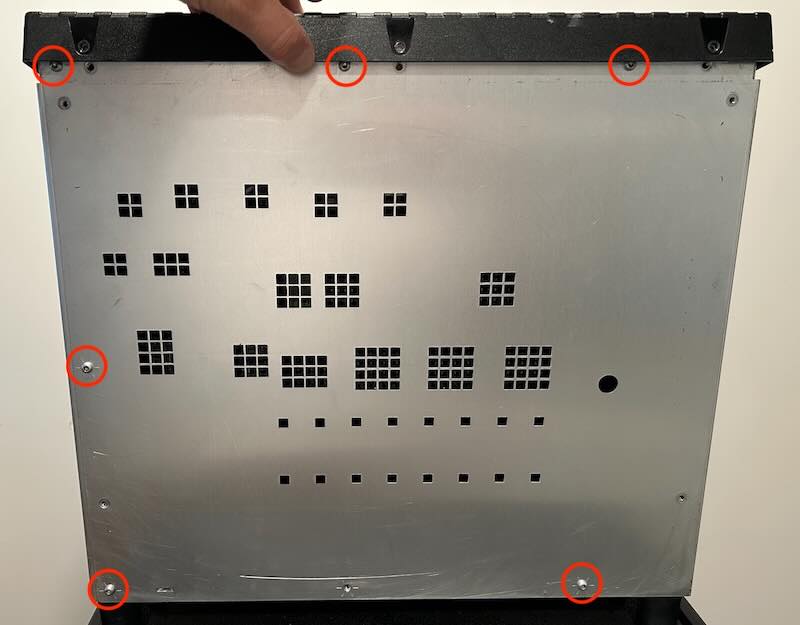
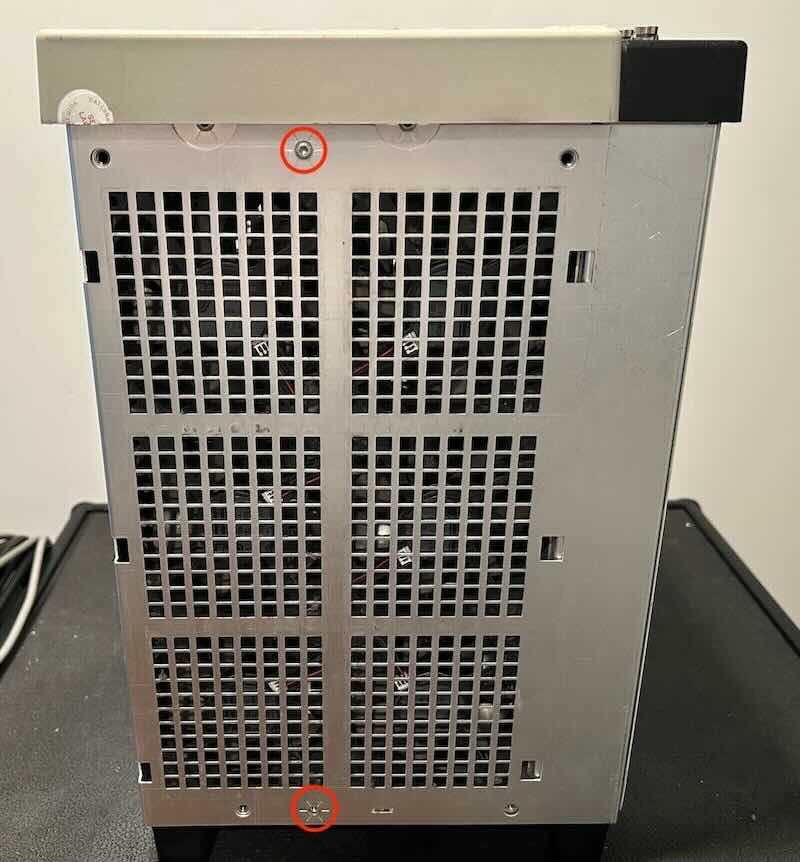
Congratulations! For those who didn’t keep track: you’ve removed 32 screws!
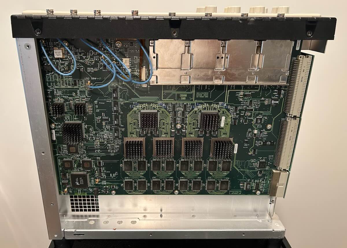
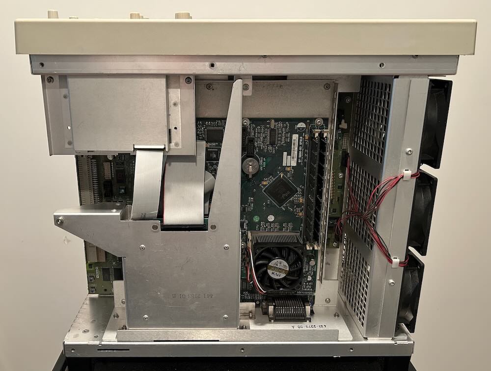
After removing the panels, you now have access to the acquisition board
at the bottom and the PC motherboard at the top:
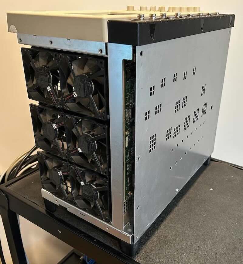
One side has nothing but cooling fans, but from the other side you can see the
power supply and an RS-232 port that you will need to connect if the backup battery
of the PowerPC controller board expires.
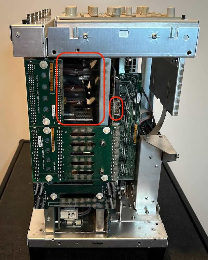
If you need access to those items, you’ve only done the easy disassembly part. On
my unit, both the PSU and the controller backup battery were fine so I was done.
Note on the picture above that the front panel has been removed. You do NOT have
to do this for pretty much all restoration cases! And you really shouldn’t.
Reinstall the bottom sheet metal cover
All of my work on the scope was on the PC motherboard and I had to put the scope
back in its horizontal position. To make sure that I didn’t accidentally damage
the acquistion board, I put the bottom sheet metal cover back in its place.
I’ve been using CompactFlash cards in the past to replace ailing hard drives. They work, but
unless you buy a more expensive “industrial” card, they don’t have built-in wear leveling support.
That is not a problem on a
Rohde AMIQ
that runs DOS, but on an OS like Windows with swap space, it could be.
So this time, I chose a 64 GB mSATA SSD ($35) and
an mSATA SSD to IDE 44 Pin 2.5” adapter ($15).
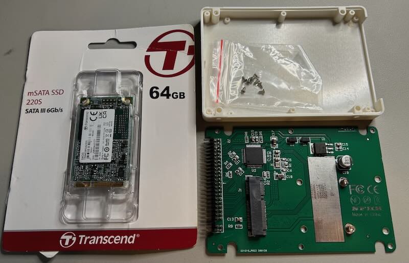
The standard way to move away from a failing hard drive to an SSD is to once again use
HDD Raw Copy Tool to write the image to the SSD and that is that. I tried that with the 64 GB SSD,
and while the scope got past the first-stage boot process, it errored out during the second
stage when it tries to bring up the Windows GUI with a STOP: c0000218 💬 error.
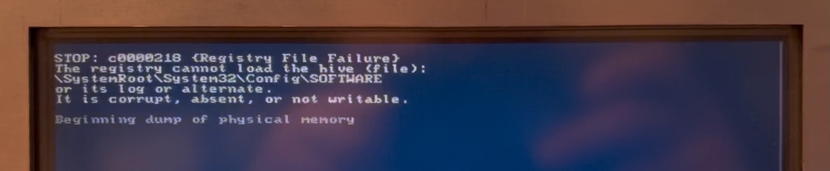
Older systems often had issues with partitions larger than 32 GB,
so I bought a 32 GB mSATA SSD instead, $3
cheaper for half the capacity, but I got the same error.
Just copying the drive image to an SSD worked fine for others, but for me it was a dead-end
that I spent many hours trying to get around. I eventually decided to reinstall all the software
from scratch, which was a whole other adventure.
I had wanted to avoid reinstalling the OS from scratch because I expected to run into
a bunch of driver issues, but in the end I had no choice. While a number of people have
reported that Windows XP can work on some of the TDS7104 motherboards, I decided to
stick with Windows 2000 Pro because I know that works and I didn’t have a pressing need
for more functionality, whatever that might be.
The scope has Windows 2000 Pro Embedded, but I wasn’t able to find an installation disk
for that and the regular version works fine too. The ISO file can be
downloaded from the Internet Archive.
The license key that’s printed on the back to the scope does not work with the regular
Windows 2000 Pro. The Internet Archive one has a key that works, and other valid keys
are just a Google away, but I didn’t even need one: I was never asked for a license key
during the Win2k installation on the scope.
The standard way to install Win2k Pro is with a CDROM drive. Unfortunately, the drive
didn’t work which meant I had to open the whole machine again to install a replacement drive.
The TEAC CD-224E
laptop drive in my TDS7104 got detected just fine by the BIOS and in Windows, but when
you inserted a disc in the drive, neither the BIOS nor Windows could read from it.
Since the RadiSys motherboard doesn’t support booting from USB stick, I decided to
replace the TEAC CD-224E laptop drive
with a ‘new’ one that I got from eBay for $20.
Unlike the hard drive, the CDROM drive can’t be removed without opening up the TDS7104,
but once the case is open, the effort is minimal. I first removed the floppy drive
to have a bit more maneuvering freedom with the cables, but it’s not really necessary.
Unplug the CDROM IDE cable
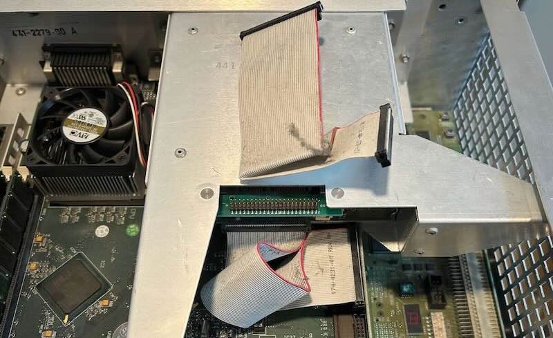
Remove 2 screws
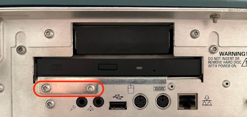
The CDROM drive sits in a metal enclosure with a small adapter PCB that converts
the CD-224E 50-pin slimline IDE connector to a standard PATA/IDE connector.
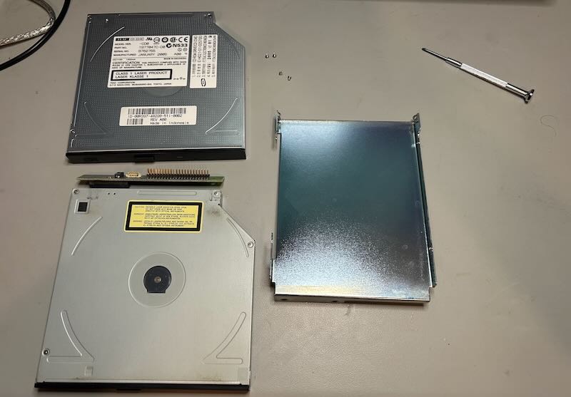
I tested the broken drive with the adapter PCB and my USB-to-IDE dongle on my laptop
to make sure the issue was with the drive and not the CDROM disc, and that didn’t work,
as expected. With the new CD-224E/dongle combo, my laptop could read the installation
CD just fine, but when I installed the new drive in the TDS7104, the BIOS couldn’t even
detect the drive! I tried every BIOS setting under the sun, but no luck.
There are many versions of the CD-224E, all with the same dimensions and slimline IDE
interface, but clearly they don’t all behave the same. The version of the broken one is version
A93 (2000), the new one is CD0 (2005). You can find A93 drives on eBay, but $69 is way too high
for something that I’d be using exactly once.
(Another dead-end)
It is allegedly possible to install Windows 2000 Pro on an old machine without CDROM
and USB port by using a virtual machine. The process is convoluted:
- mount the installation CDROM ISO and the SSD onto the virtual machine.
- go through the first phase of the installation process until asked to reboot.
- now move the SSD to the old the machine (the scope) and proceed with the installation
there.
I once again spent a few hours getting this to work, but the scope never managed to
make it to the Windows installation GUI.
Alright, so I’m running out of options and USB is about the only storage interface left.
The scope can’t boot from a USB stick directly but there is a way around that.
Let’s first create a bootable USB stick with the Win2k installation ISO on it.
Most of the time, you can use a utility like
Balena Etcher
to burn a CDROM ISO onto a USB stick, but of course that doesn’t work for the Windows
2000 Pro installation CDROM.
Instead, you need to use WinSetupFromUSB
to prepare the USB stick:
- Download, install, launch
- Select the USB stick as target
- Select Auto format with FBinst and use the FAT32 file system
- Add to USB disk: Windows 2000/XP/2003 Setup
- Select the mounted Win2K Pro ISO drive as source
- Press “GO” to copy Win2K Pro onto the USB stick
Plop Boot Manager
makes it possible to boot from a USB stick on machines that don’t support it.
It goes like this:
- copy the
plpbt.imgimage from theplpbt-5.0.15.ziparchive to a floppy disk
with a tool like WinImage, Rawrite32,
or RawWrite for Windows. - boot the Plop Boot Manager from floppy disk.
- the boot manager has a USB mass storage device driver
- select USB as boot device
I tried hard to avoid the floppy disk route because my experience with floppy drives on
old test equipment has been abysmal: none of them worked. Having no choice, I tried to copy
the boot manager image with my USB floppy drive and… that didn’t work either. All these years
the USB floppy drive, freshly bought from Amazon, was the culprit!
Since the scope still worked fine with the IBM HD, I used its own floppy drive to
put the image onto the floppy disc and that worked.
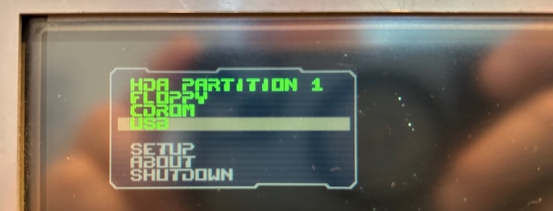
After setting the BIOS to allow booting from floppy, the scope booted into the
Plop Boot Manager just fine and it was able to boot the USB stick with the Windows 2000
Installation ISO.
Plop doesn’t support USB hubs. The RadiSys motherboard has only 1 USB port which will
be occupied by the USB stick, so you’ll at least need a PS/2 keyboard to do anything.
With the empty 32GB SSD plugged into the scope, the installation of Windows 2000 Pro was uneventful.
There are 2 phases: the first one uses text mode and primarily copies all the necessary drivers
onto the SSD. The machine then reboots and continues the installation in Windows GUI mode from the
SSD, though the USB stick is still needed in a later stage.
The TDS7104 has a bunch of specialty hardware that needs dedicated drivers, but those are not
needed to get the OS up and running.
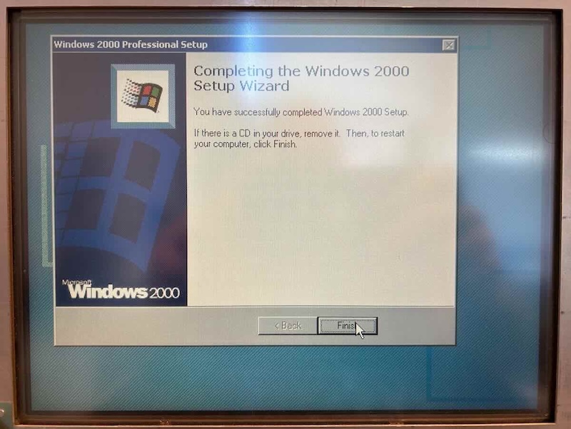
At long last, I was able to see this image:
There is a great GitHub repo
with a bunch of TDS7000-series software, including this
Drivers directory.
The README.md says that the driver should work for Windows 98 and XP, but
the Chips and Technologies video driver definitely did not work for Win2k!
I used Driver Collector
to extract drivers from the original hard drive and that worked fine. You can find these drivers
here.
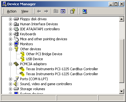
The 4 specialty drivers are for these components:
-
Front panel
This is the USB Device that’s listed under “Other Devices”
-
Texas Instruments PCI-1225 CardBus Controller
You need to install this driver twice, once for each port.
Windows installed a default PCI-1225 driver for this, but that one doesn’t
work, hence the exclamation mark next to it. The name of the driver.inffile
isunsup.inf, for unsupported? Confusing, but that’s the one to use. -
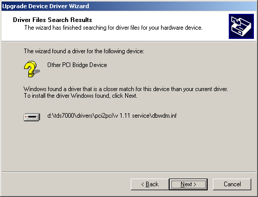
PCI2PCI bridge
That’s the Other PCI Bridge Device.
-
Chips and Technologies 69000 video driver
The default Windows driver for the C&T 69000 is what makes the screen work
when running Windows, but it’s not sufficient to render measured signals
in the TekScope application. For that, you need to update to the
Chips and Technologies (Asiliant) 69000 driver.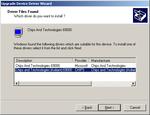
The TDS7104 and TDS7054 firmware v2.5.5
can be freely downloaded from the Tektronix website. The installation was painless, just launch
the executable.
The TDS7104 has a convoluted architecture where the PowerPC on the controller board can access
files on the hard drive of the regular PC that are located in the c:\vxboot directory. Since the
controller backup battery on my scope was still in good condition, I didn’t have to do anything special:
the vxboot directory was created automatically during the firmware installation.
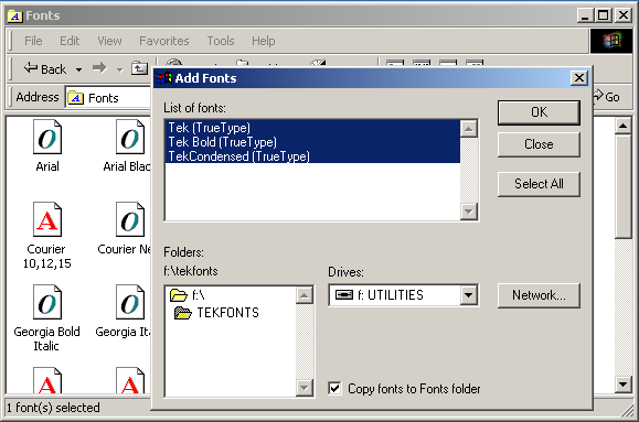
The Tektronix scope application uses custom TrueType fonts to render some of the symbols
screen, e.g. the rising edge trigger symbol. Without those fonts, it will show some
Greek characters instead.
To fix that, you need to download the tekfonts.zip
file, unzip it, and install the 3 fonts.
Despite rendering those Greek characters, those font files were already installed on the
new system, so I had to delete them first and reinstall the new file. Things looked good
after that.
To delete or install the fonts, do Start -> Settings -> Control Panel -> Fonts.
And with that, I finally had a working TDS7104 with SSD!
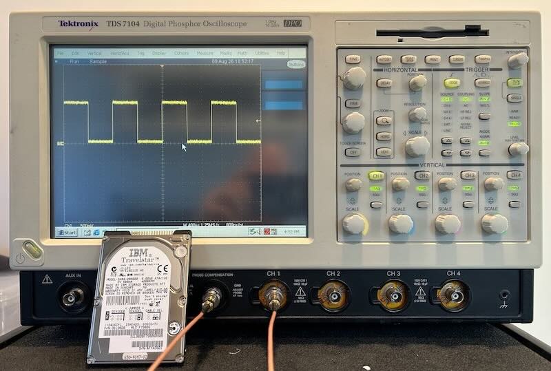
The time from pressing the power button to having a waveform on the screen was much lower
too: from 2min50s down to 1min35s.
One thing was missing, though: the advanced jitter license option.
The same GitHub repo that I mentioned earlier also has an unlock options
directory with scripts to enable and validate license key features. On the Eevblog forum,
plenty of people have been able to use it, but it’s not as user-friendly as other license key
schemes.
Most of the time, license keys are additive, with one license key per feature that must be
enabled. On the TDS7104, there is 1 license key that enables all features at once.
The validate script shows how that works with the license key and serial number of
my scope:
./validate.py BREHZ9885D3MNKXHHYQCQRGQRW7C
E1 91 73 BF F7 7B E4 C5 52 3D C7 3A E1 9E 71 8F 76 01
44 2F 54 00 00 C0 1B 79 48 00 00 00 00 00 00 00 00 A8 16 30 00 10 00 00 00 00 00
This key is for UID 1BC00000542F (S/N 21551, model TDS/DSA/DPO7104):
CRC: 4879
Key is valid, active options:
00 00 00 00 00 00 00 00 08 00 00 00 00 00 00 00 00 00
We can see how that long string of gibberish contains:
- the serial number 21551
- the model number TDS/DSA/DPO7104
- a UID that is really just a combination of the serial number and the model
- a CRC
- an 18-byte or 144-bit bitmask
I can recreate the license key by feeding these parameters back in the generation tool:
./gen.py tds7104 B021551 000000000000000008000000000000000000
XBGDV-K8GDM-KH7X3-979Y9-ZZ593-9ZRZZ-4837X-9VV5Z-T9HB
I had to join the 18 bytes into one 72-digit hex number.
The license key that comes out doesn’t match the original one, but after entering
it into my scope, it worked just the same:
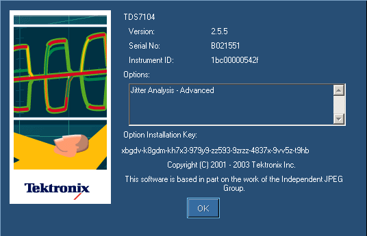
The scope is very forgiving about the license keys: upper case, lower case, dash or no dash,
it all seems to work. You can even reduce the number of hex digits in the license enable
mask to a certain extent, and the license key will still work:
./gen.py tds7104 B021551 000000000000000008000000000000
7GWUZ-RRRMK-59LYT-978Y8-GZD93-8ZQGZ-C836X-8CVD
What remains is the question which bit maps to which feature?
This post in the eevblog forum
has you partially covered here:
########################################################################
4
# options masks/names/descriptions, conversion functions
5
6
# 01 - 1M
7
# 02 - 2M
8
# 04 - 3M
9
# 06 - 2M 2A
10
# 08 - 4M
11
# 00 00 00 00 00 00 04 - USB
12
# 00 00 00 00 00 00 20 - JT3
13
# 00 00 00 00 00 00 00 80 - ET3
14
# 00 00 00 00 00 00 00 00 08 - JA3
15
16
# 00 00 05 00 00 00 00 00 00 10 - ASM DDRA DJA
17
# 00 44 00 00 00 00 02 08 - SM ST J1 J3E
18
# 04 40 00 00 00 00 06 C0 10 - 3M JT2 USB2 ST
19
# 04 44 FF 03 00 00 8D A3 EF FF 17 - 10XL, MTH, PTH1, ASM, LT, DDRA, SLE, EQ, TDSDDM2, TDSUSB2, YDSCPM2, RTE, IBA, PCI, TDSDVI, TDSET3, SAS, TDSHT3, TBD, JA3, TDSPTD, TDSVNM, DPOPWR, TDSHT3v1.3, 73, 74, DJE, DJA, 77, 78, 79, SVE, SVP, SVM, SLA
Note how JA3, advanced jitter analysis, indeed has bit 14 set to 1.
Some people just use a mask of FFFFFFF....FFFF.
Some of these analysis tools can once again be found in the same GitHub repo, or on the Tektronix
website.
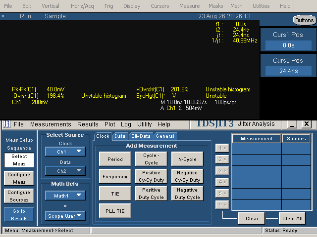
This is all theoretical, of course. I don’t think I’ll ever have a hobbyist need for
any of this…
The final act is cleaning. This scope was in exceptional condition, except for the knobs
on the control panel.
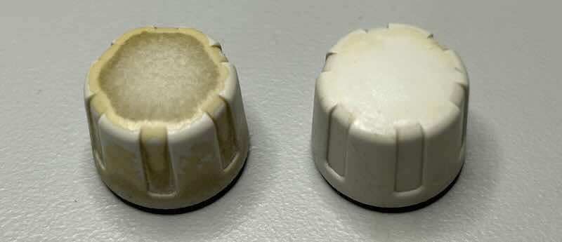
The knobs have a thin anti-slip layer on them that is a finger grease magnet. Removing that
layer with isopropyl alcohol makes the knobs look like new without a noticeable difference in
control. Just be careful about using 99% isopropyl, I think it attacks the plastic. 90% was
fine.
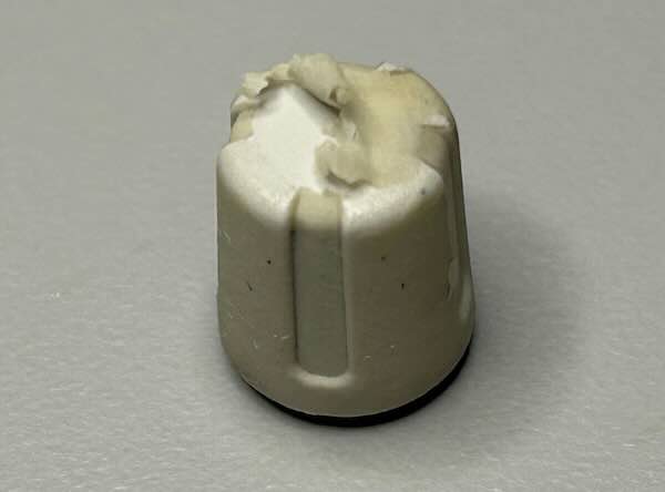
If some knobs are missing or cracked, the ones of a TDS220 are identical. You can buy knobs
new or on eBay, but they’re expensive. If you really need a few, you might be better off buying
a donor TDS220 instead.
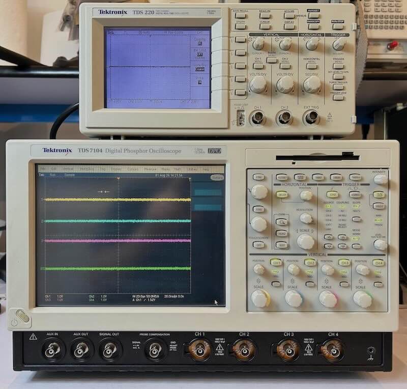
And with that, the scope is ready to be deployed to a shelf in my garage. One day I’ll
need something with this kind of firepower but for everything else, a small scope with
lower specs is way more practical. I like the scope better than the Agilent 54831 so that will
probably hit Craigslist at some point.
All words in this blog posts were written by a human.
⚡ **What’s your take?**
Share your thoughts in the comments below!
#️⃣ **#Refurbishing #Tektronix #TDS7104 #Oscilloscope**
🕒 **Posted on**: 1788293726
🌟 **Want more?** Click here for more info! 🌟
